Making an antenna for a 4G modem
After calculation, I proceed to the manufacture of antenna parts. Special care is needed when bending the antenna wire itself and making the balun.
Bending the wire
I never doubted for a second that I couldn't just take and bend the wire in compliance with all radii and distances, so on my CNC3018 I made a template where the finished antenna wire should go without effort:
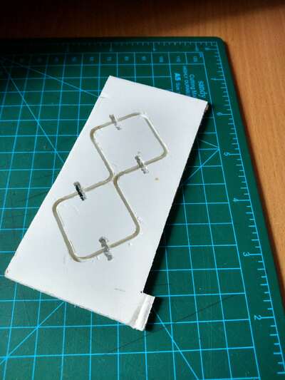
Practice has shown that this thing is useful for the final alignment of the antenna, but it does little to help bend it. It made sense to make one separate corner to bend the wire only on it, but now this is no longer relevant to me :)
I'll see how long the copper wire I need:
octave:2> quad_size*8
ans =  224.38
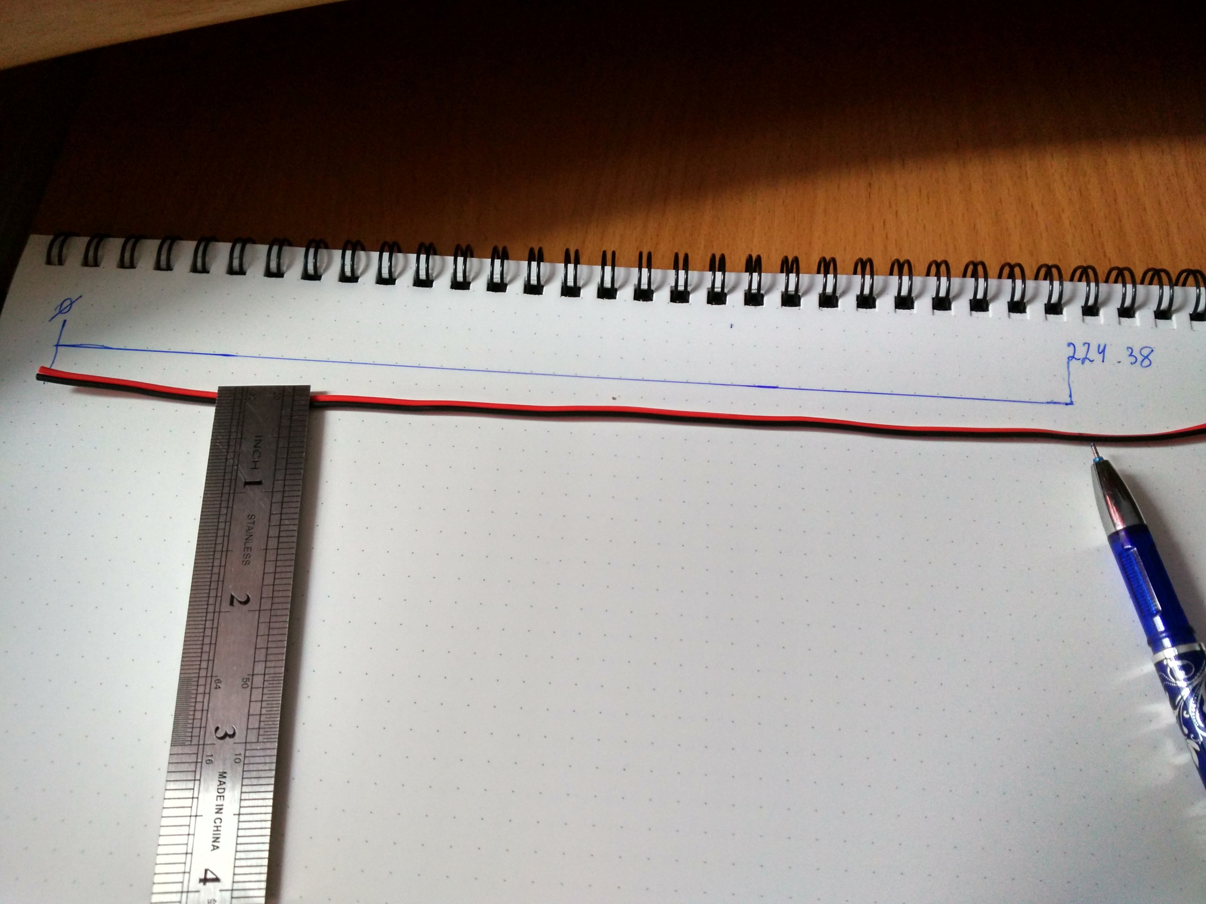
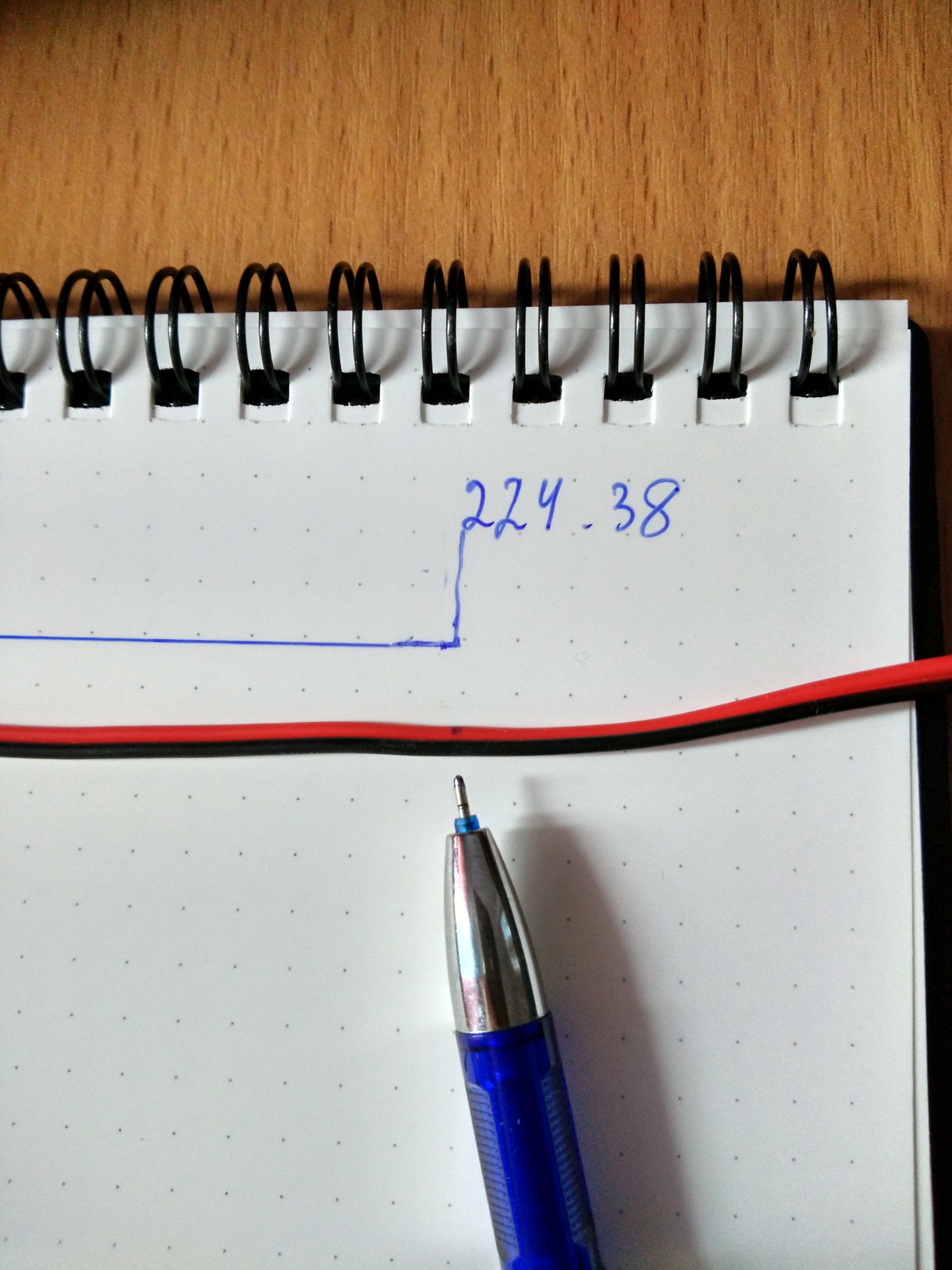
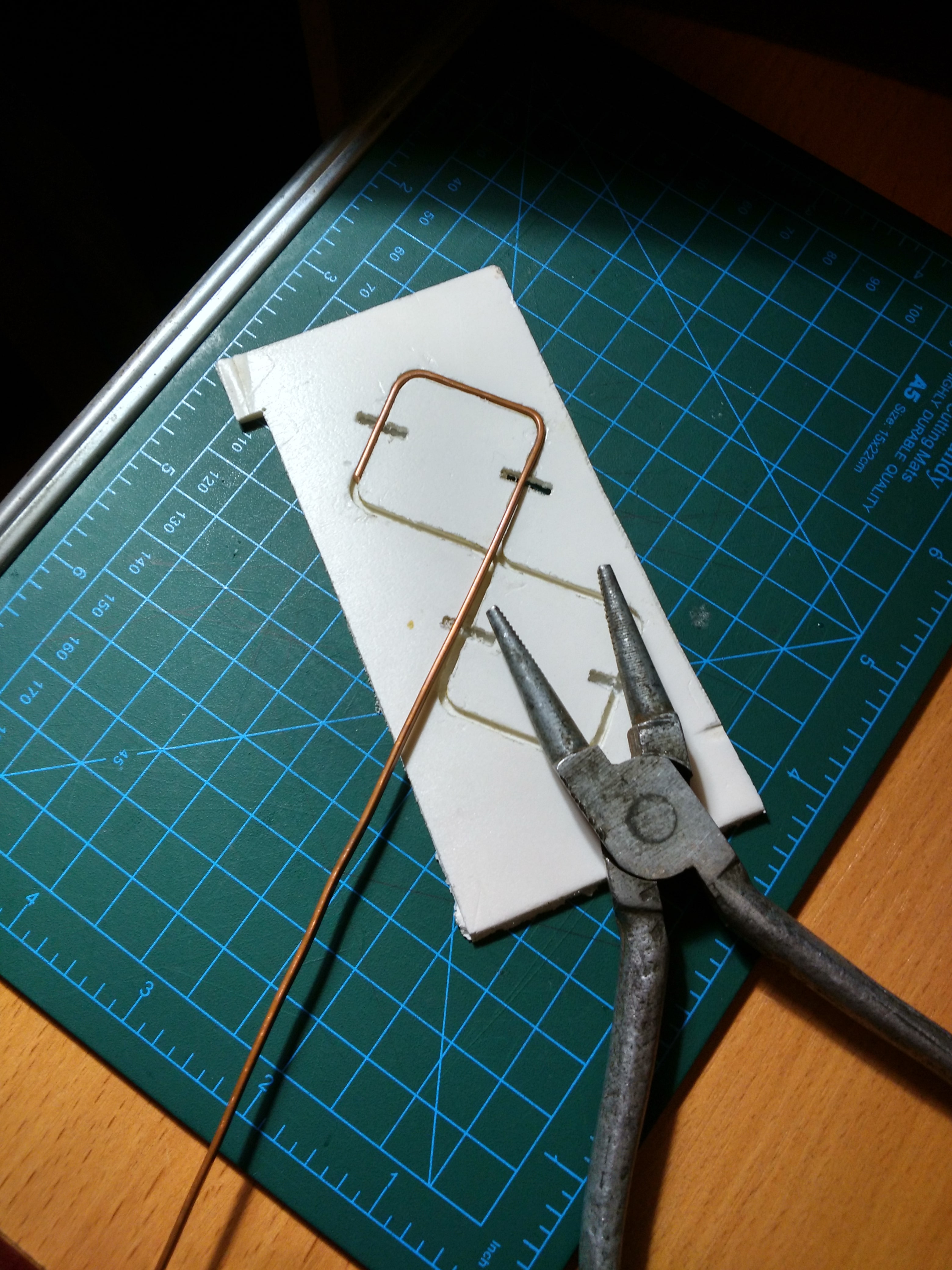
I'll mark this distance in a notepad and put a simple 22AWG into the template:
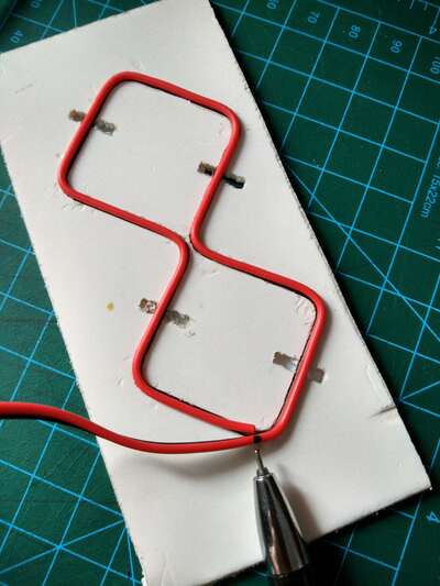
The mark must match the drawing in the notebook:
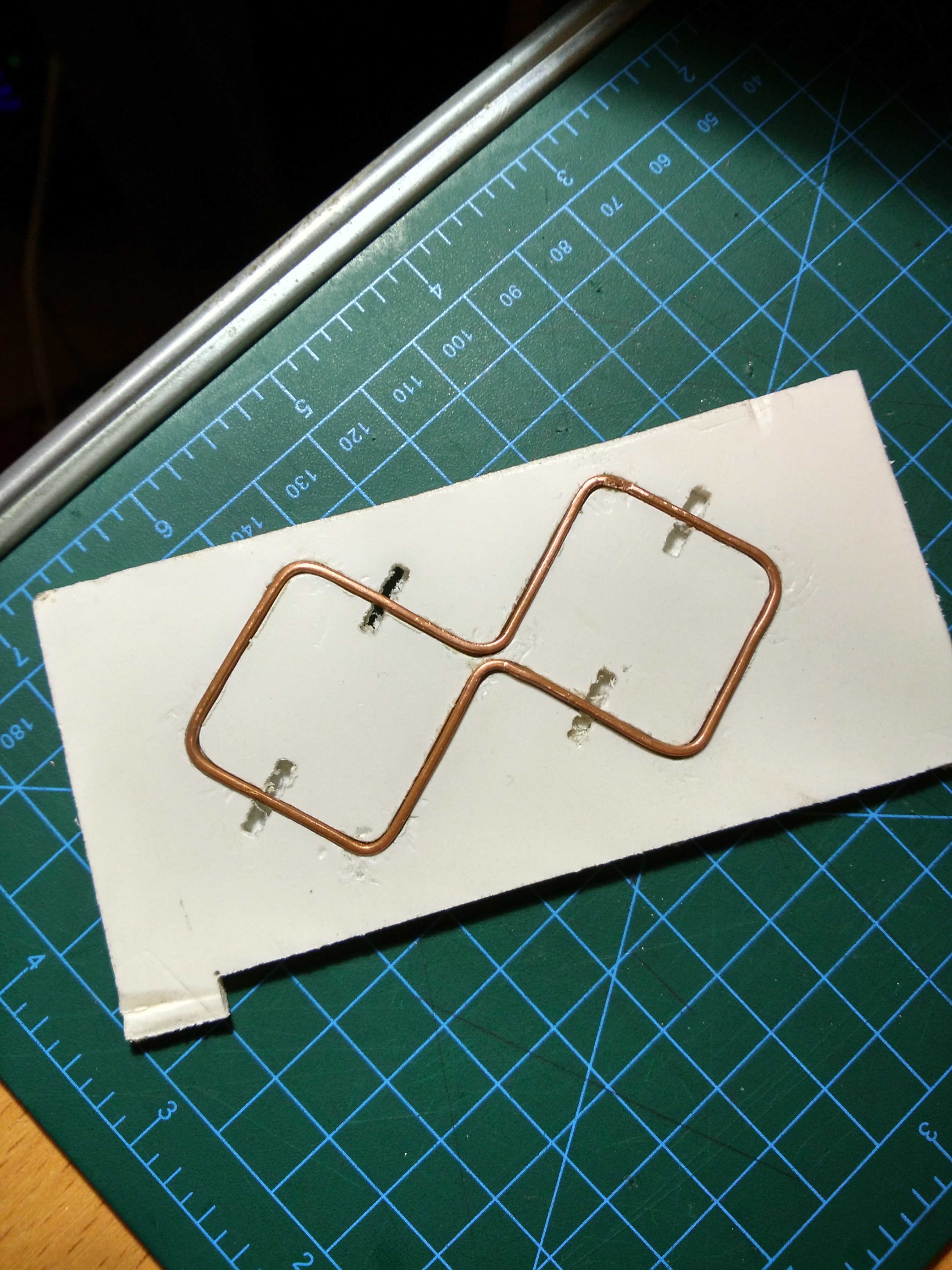
Bend the copper wire carefully:
I solder the antenna straight away.
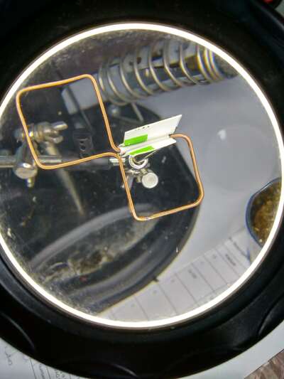
Balun
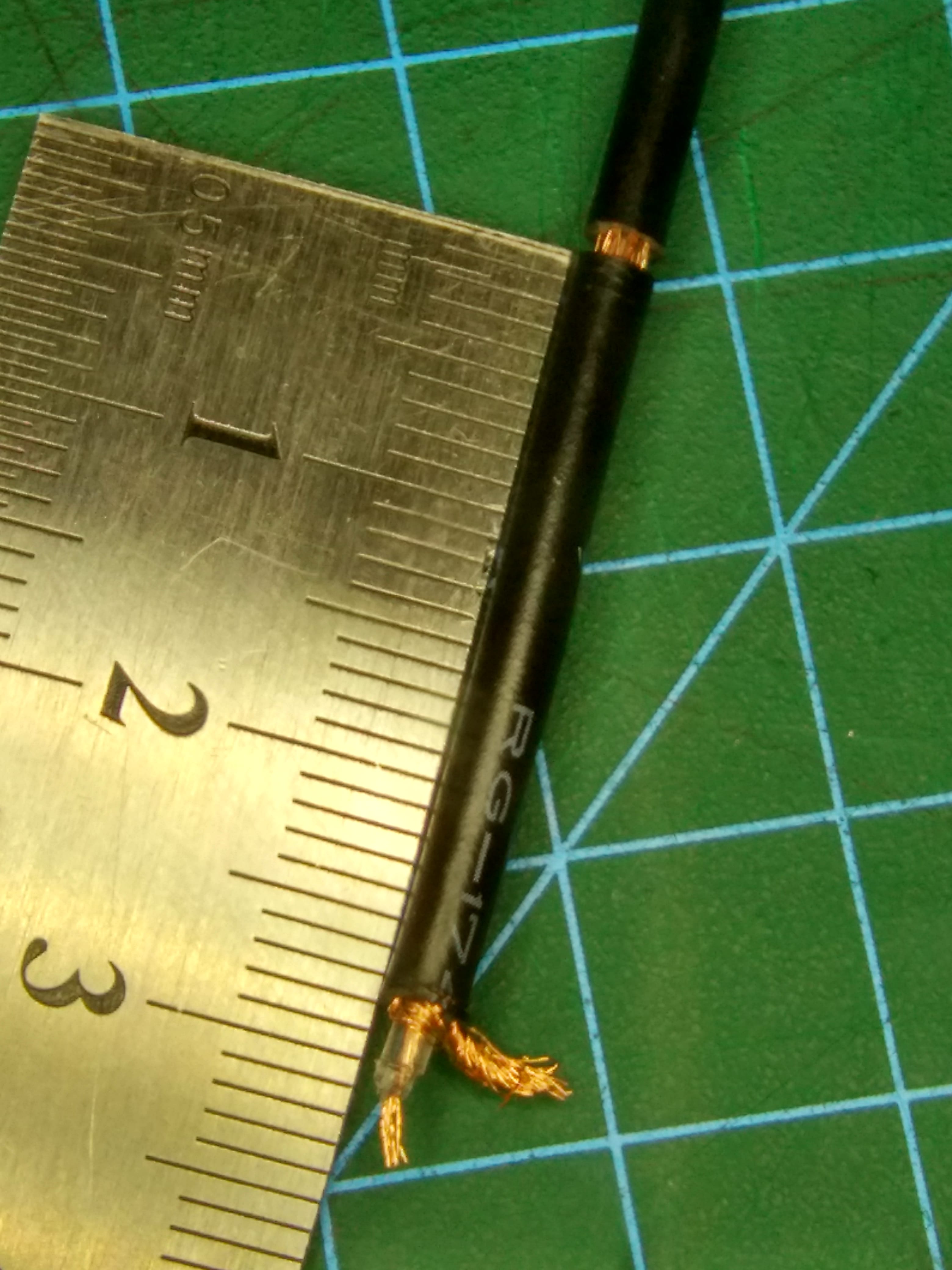
The RG174 cable will be connected directly to the antenna (the diameter of the first shield is 1.98mm, the diameter of the jacket is 2.79mm). I considered using a bazooka balun, but two considerations made me abandon this idea:
- I do not have a tube with a diameter of mm, namely with this ratio of diameters this type of balun becomes effective;
- the bazooka balun is connected around the circumference of the coaxial cable screen at a certain distance ( or less if the balun is folded) from the vibrator, I very much doubt that I can do this accurately and evenly around the entire circumference of such a small wire. I have seen and read about options when the balun is connected directly to the vibrator, but I think that with such a connection the balun turns into an additional vibrator, and I really do not want to repeat the calculation of the antenna taking into account this vibrator surface.
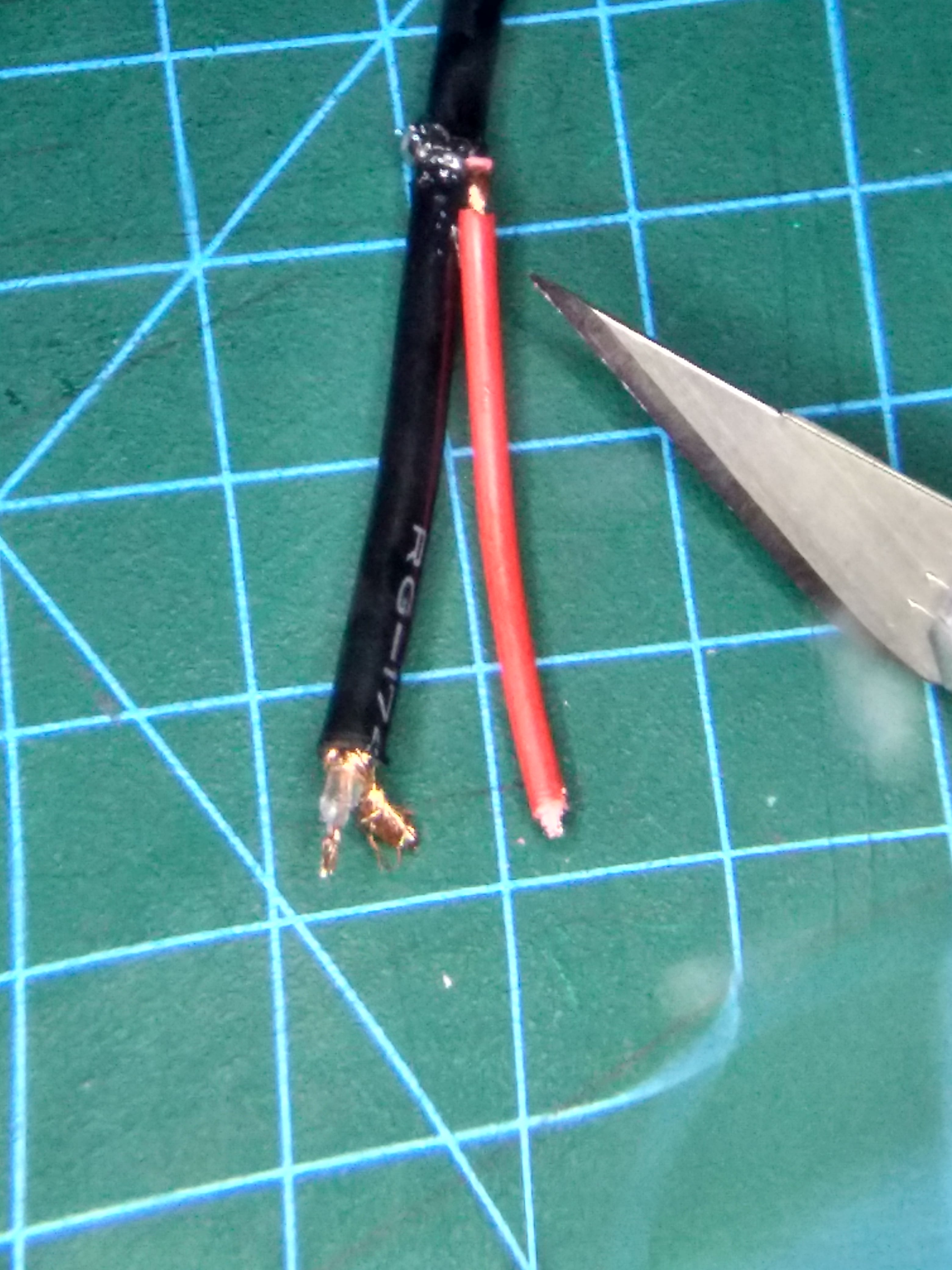
So I decided to implement a less efficient, but easier to manufacture balun from a piece of wire.
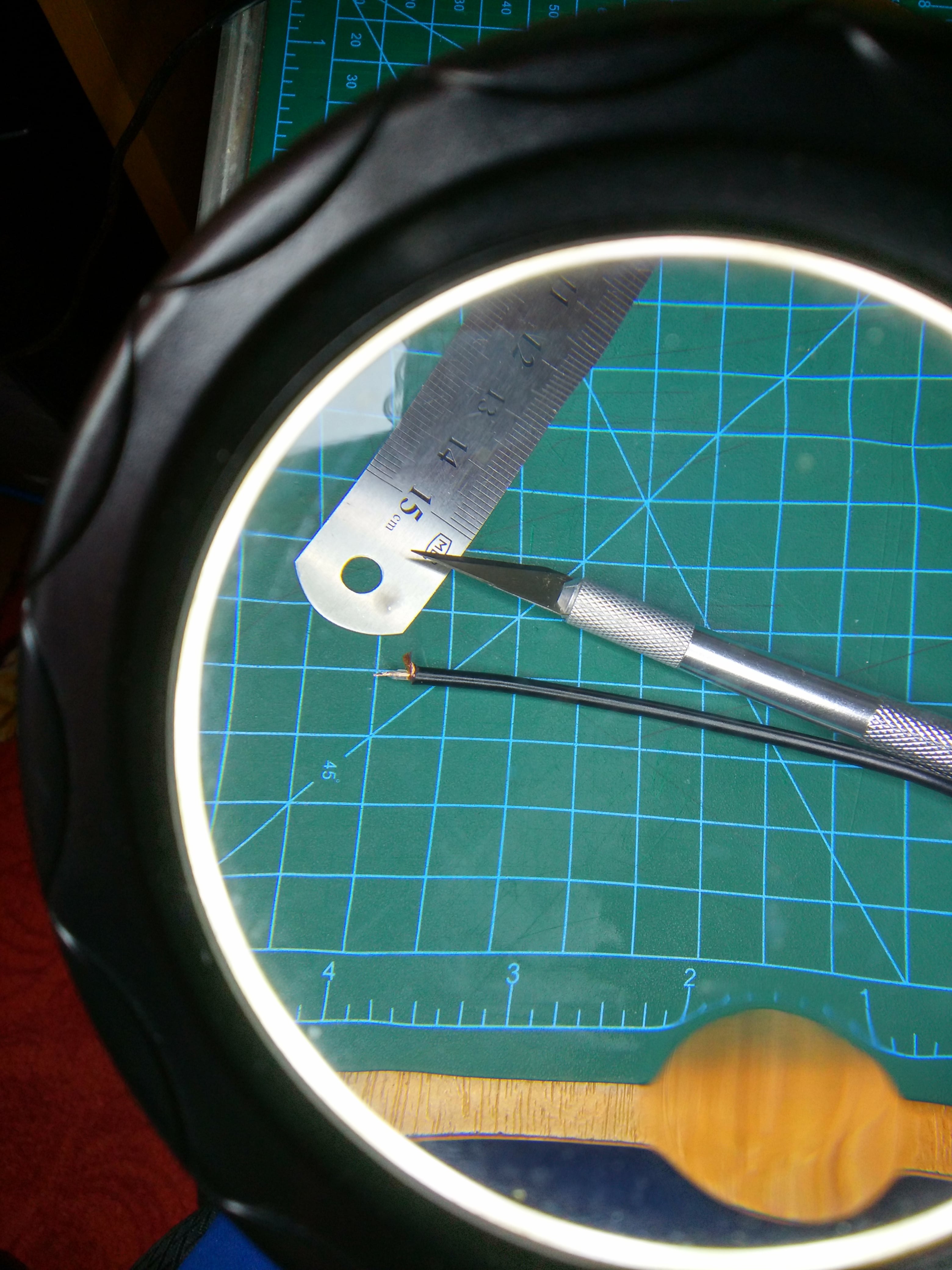
In addition to careful manipulation of the outer sheath of the coaxial cable, it is advisable not to overheat the shield: the internal dielectric may melt and the characteristics of the cable may deteriorate.
Reflector
Now I can move on to other structural details. This is what the antenna looks like in FreeCAD:
The two vibrators are positioned at an angle of to each other and at to the horizon.
The antenna was conceived as hanged from the ceiling on a wire loop - two triangular combs at the top of the reflector allow you to choose the antenna angle in the horizontal plane. The modem cradle has a cutout for the USB cable and there are also two hooks to gently secure the top of the modem.
Few details should be placed on the face of the reflector to minimize disturbance to the reflective surface, which, by the way, is an ordinary foil for baking all sorts of delicious things.
The most important part of the reflector is the vibrator posts. They perform an important function of maintaining the calculated shape of the vibrators and the distance between the vibrators and the reflective surface of the reflector.
Now I will say about the material of the posts. While all other parts of the antenna can be made from almost anything, the vibrator posts must be radio transparent at the antenna frequency. My frequency is close to the radiation inside the microwave, so heating a piece of plastic for a couple of minutes showed its suitability (there is no charring and other unpleasant manifestations of interaction with radiation). It is believed that at the points of zero potential, you can use any material for the posts, up to metal, sometimes the posts are even soldered to the reflector. I don't do this for the following reasons:
- I doubt that I will ideally make vibrators, so the point of zero potential will not be such;
- I calculated the antenna based on the air insulation between the vibrators and the reflector. If you use metal posts, then you need to calculate and simulate with these additional vibrators.
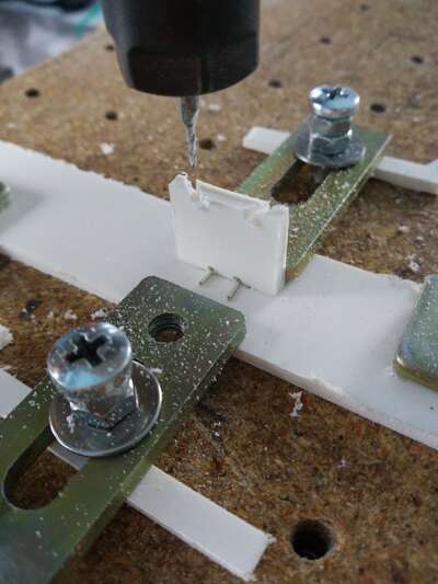
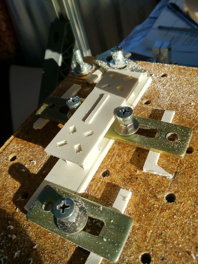
I don't have a 3D printer, so making posts is a fun task. I had to make an auxiliary clamp to accurately cut the grooves on the ends of the posts:smile: Here's the first clamp, unsuccessful:
Second clamp with reinforced rigidity:
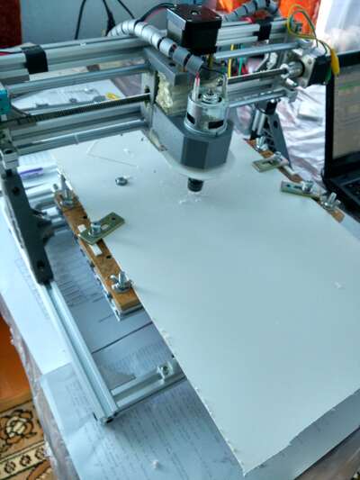
The reflector is much larger than my CNC3018, but this can be solved:
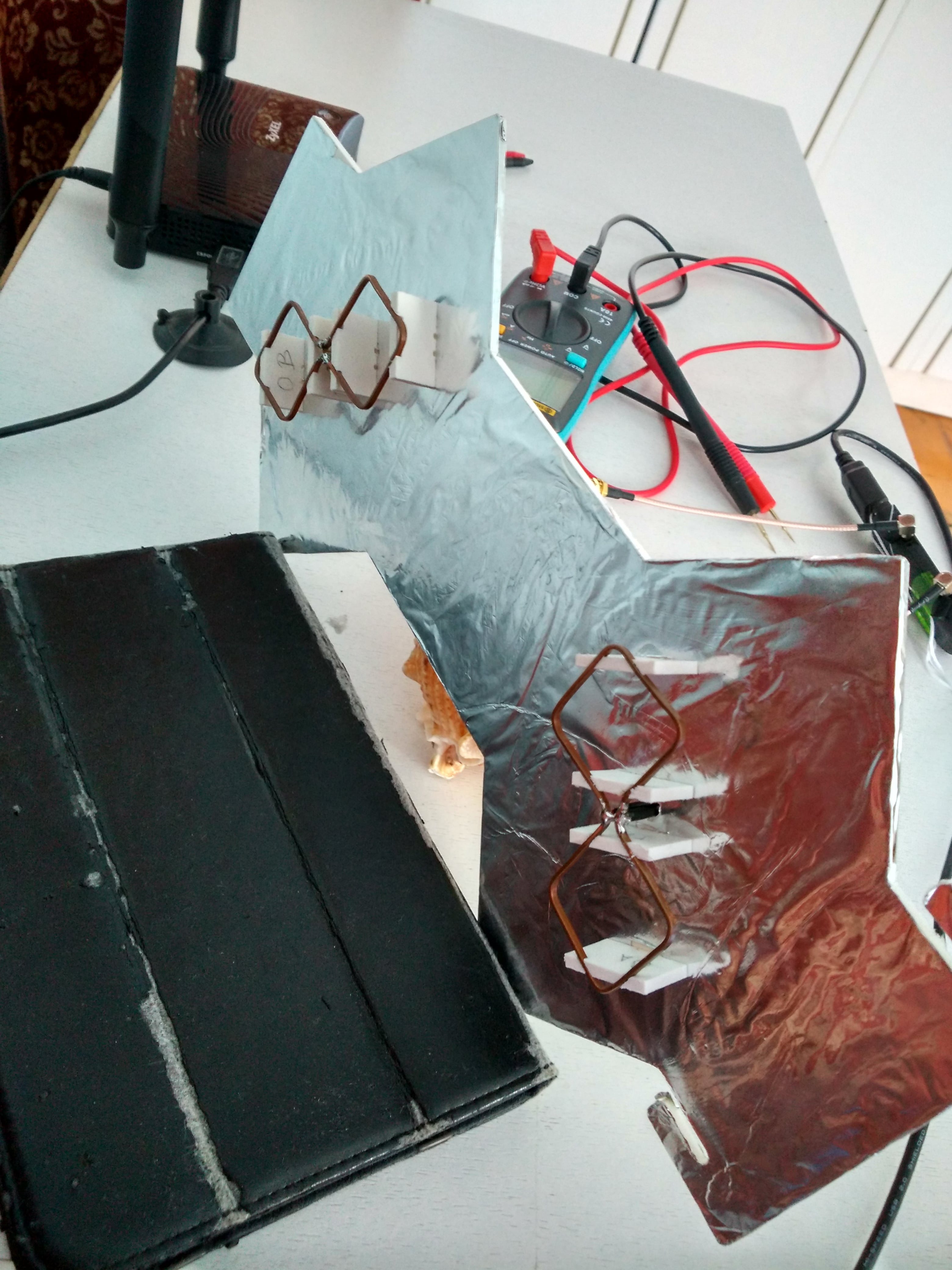
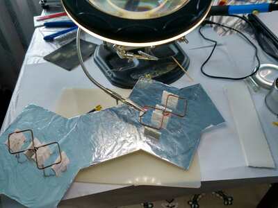
Soldering cables and baluns to vibrators, the last step before exciting antenna testing:
Testing
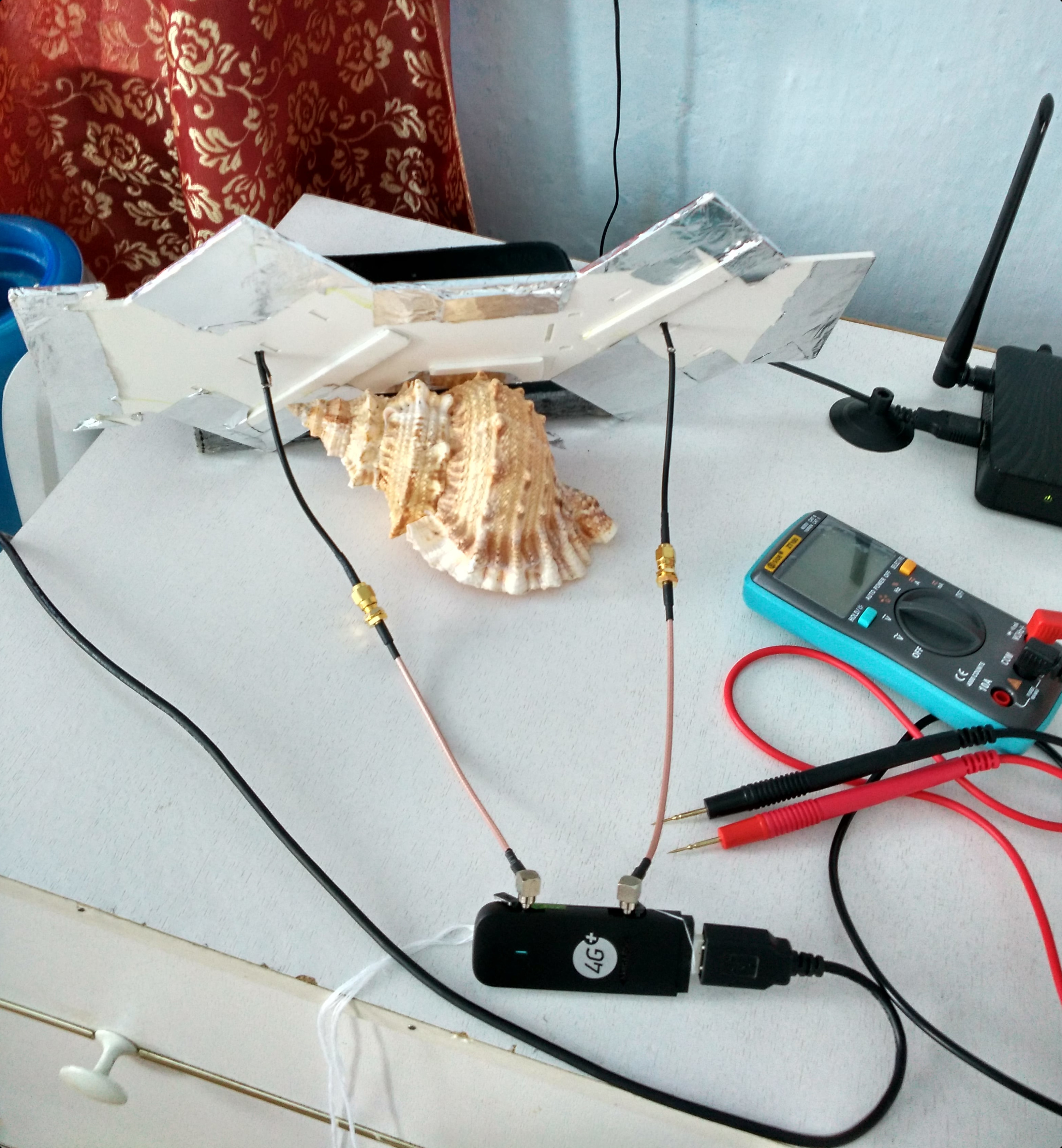
Rear view will not receive design awards :)
Huawei modems have a convenient mechanism for assessing signal quality on the page at http://192.168.8.1/html/antennapointing.html
So just a modem without an antenna:

Modem with antenna:

Excellent! The receiving conditions changed and went into a completely green area. LTE Signal Parameters Reference.
